Surface Test Tree
Surface Test Tree, also called Flowhead, is located directly on top of the well and is the first piece of equipment that fluid from the well flows through. Its principal function is to control the fluid flow in and out of the well.
Surface Test Tree
Surface Test Tree, also called Flowhead, is located directly on top of the well and is the first piece of equipment that fluid from the well flows through. Its principal function is to control the fluid flow in and out of the well.
The flowhead consists of four gate valves: a master valve, two wing valves (flowline & kill line), and a swab valve. A swivel below the main block of flowhead allows drill stem to rotate freely, while the test tree remains stationary. And there is another type which mater valve below swivel.
The Surface Test Tree can be adapted to connect to various sizes of tubing or drillpipe through the use of a crossover sub.
Each tree is supplied with a handling sub to enable rig elevators to raise and lower the tree in the derrick. Flanged 45° support subs on the kill and flow wing sides of the central body enable flexible flow lines to be easily connected to the Surface Test Tree.

Application
Pre-completion testing
Drill Stem Testing
Well Cleanup
Well simulation
Onshore and offshore well testing
Design Code & Standards
Supports the weight of the test string.
Protection frame on main block for manual and hydraulic valves improves durability.
Flapper or dart check valve is set on inlet of killing line
Master valve can be located below swivel or integrated in main block
Swivel enables rotation of the test string for packer setting and disconnect operations.
Adaptable and compact design provides added flexibility and mobility.
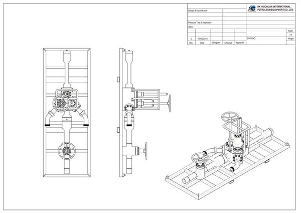
Technical drawings

| Design Code | API 6A, ANSI B31.3, NACE MR-0175 | |||
| Size | 3.1 / 8" | 3.1 / 16" | 3.1 / 16" | 4.1 / 16" |
| Pressure Rating | 5000 psi | 10000 psi | 10000 psi | 15000 psi |
| Temperature Class | P-U | |||
| Material class | To be advised | |||
| Upper Connection | As required | |||
| Lower Connection | As required | |||
| Kill Connection | 3" Fig. 1002 F | 3" Fig. 1502 F | 3" Fig. 2002 F | 3" Fig. 1502 F |
| Flow Connection | 3" Fig. 1002 M | 3" Fig. 1502 M | 3" Fig. 2002 M | 3" Fig. 1502 M |
| Service | Oil & Gas, H2S Service | |||

