Filter Separator
Filter Separator
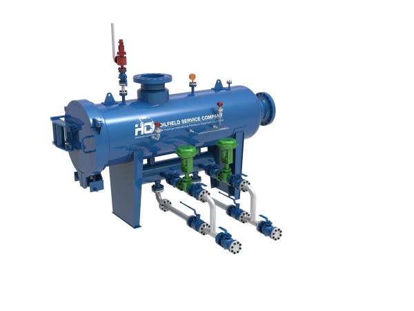
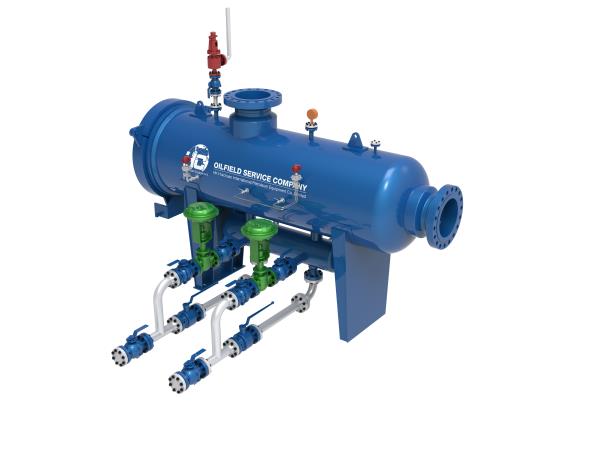
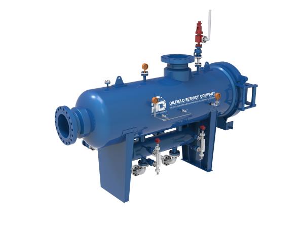
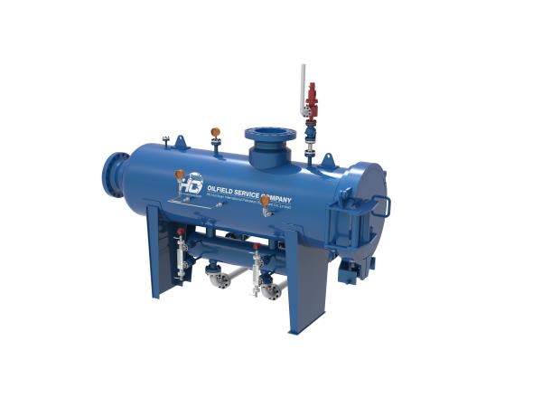
Filter Separator is used to remove liquid, small solids (created by the tubing and wing erosion) and other particles from the flow steam. Filter separators, like other gas-liquid separators, can be horizontal and vertical; the most common type is horizontal. If there is a large amount of water in coming gas, structure of filter separator is designed to have a “boot” in the bottom of the separator connected with two similar tubes parallel to each other. Retention period required between 3 and 5 minutes for hydrocarbon (oil)-water separation by settling. Sizing the dimension of the filter separator’s each section depends on the calculations and design of manufacturer or engineering company.
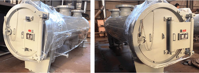
Filter separator consist of coalescing filters and mist extractor inside of its vessel, usually have quick opening closures for maintenance and replacement of the filters.
“Filter separators and coalescing filters are required, when droplet sizes below 3 microns”
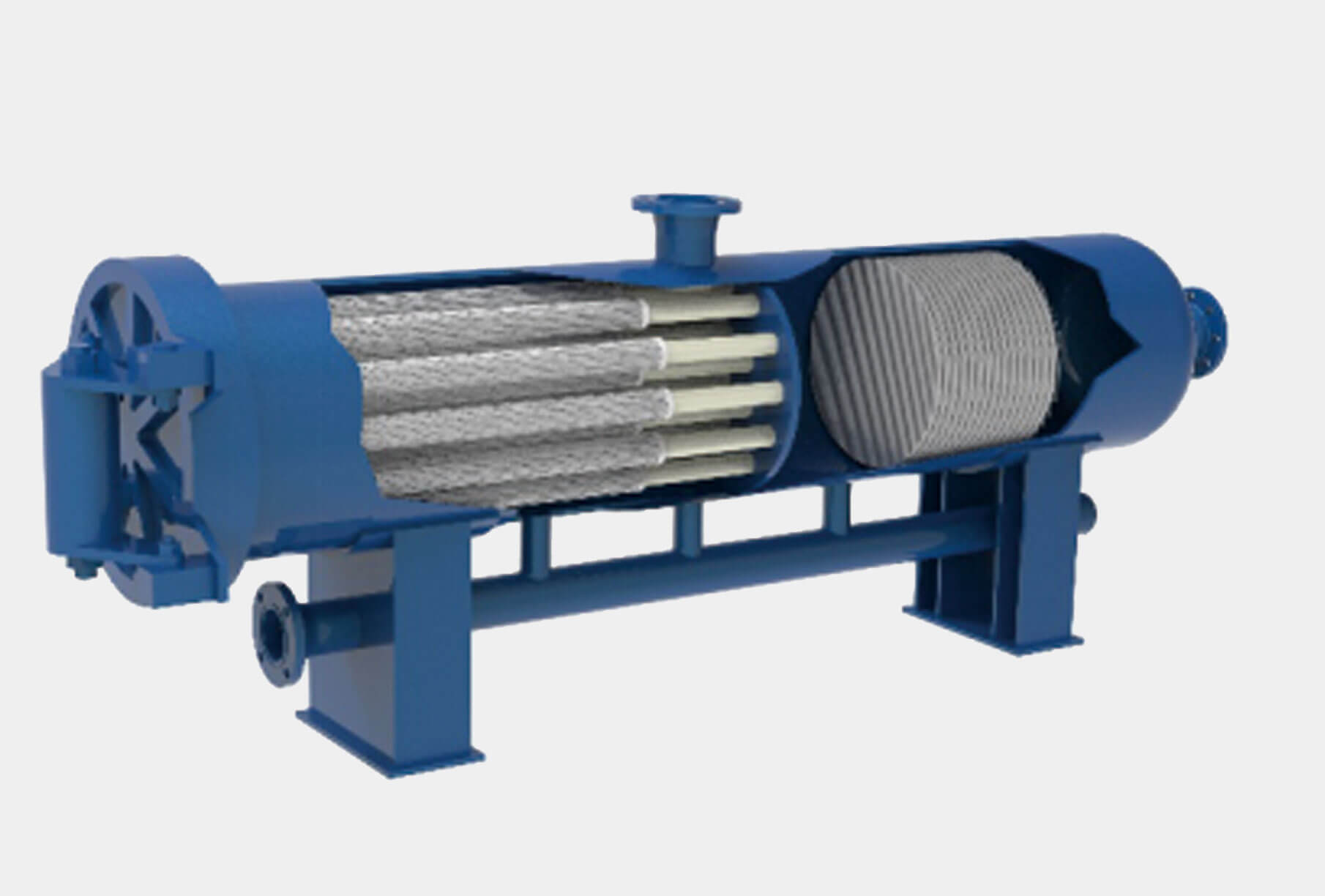
- Typical Horizontal Filter Separator
Filter separators have a wide application in gas pipelines, as well as the gas processing plants, for example, acid removal units, when after passing filters separators catch the liquids and condensed hydrocarbons coming from the absorber. In gas processing, adequate inlet separator and filter separator are required to prevent foaming due to the chemical contamination. If absorber is downstream from amine unit, glycol unit, or compressor, a filter separator is required. Also, filter separator and coalescing filter used to prevent fine mists from entering the absorber.
Solid removal efficiency of the filter separator is 100% when size of solids is 3 microns & larger, and 99%, when size of solids are 0.5-3 microns, while liquid removal efficiency is 98% when size is 8 microns & larger.
Efficiency of filter separator depends on particle size, distribution of particles, and liquid loading.

- Typical Horizontal Filter Separator
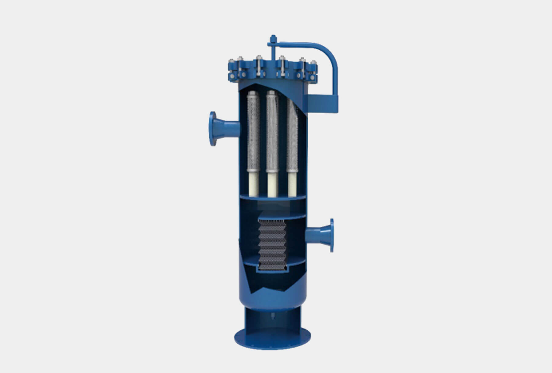
- Typical Vertical Filter Separator
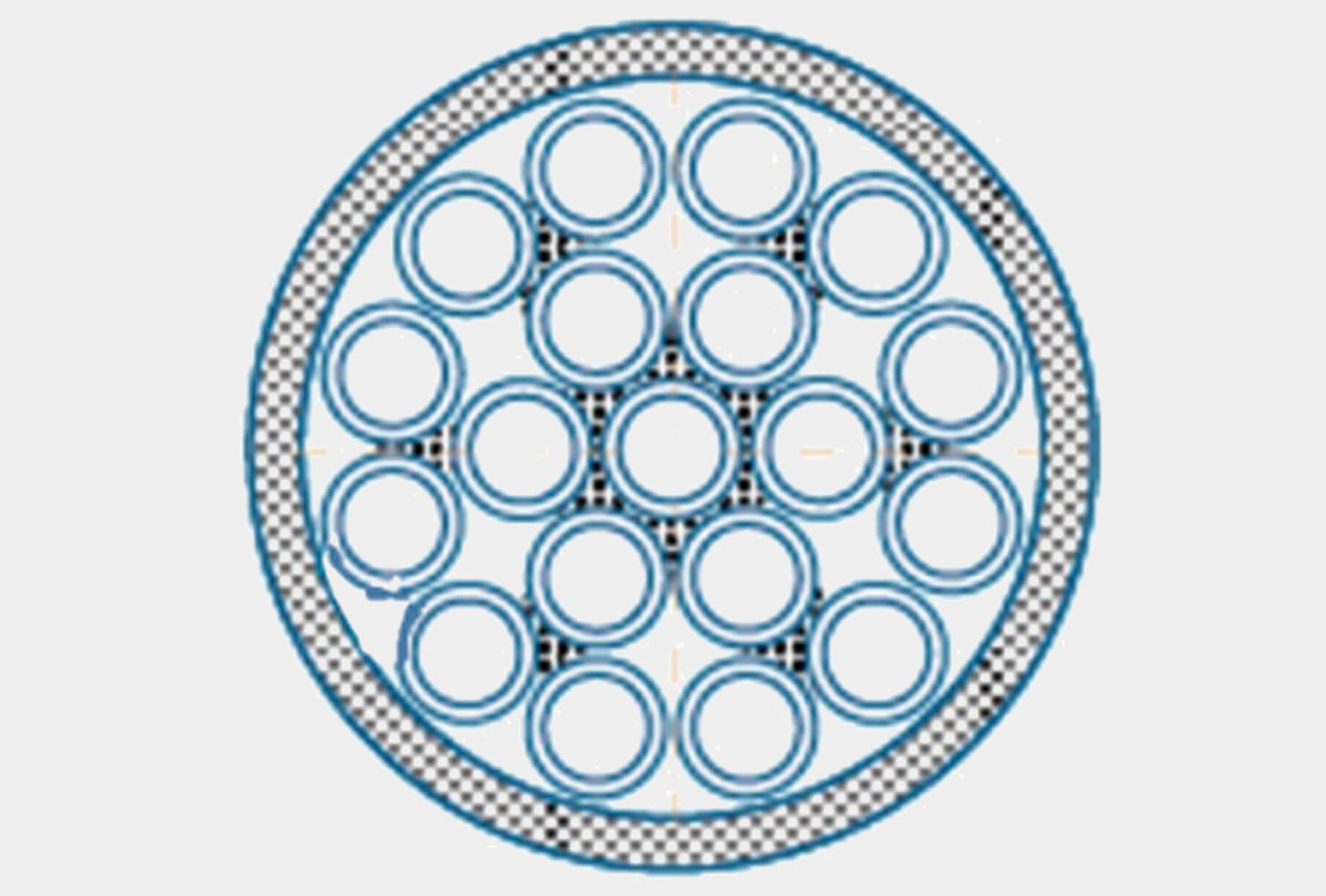
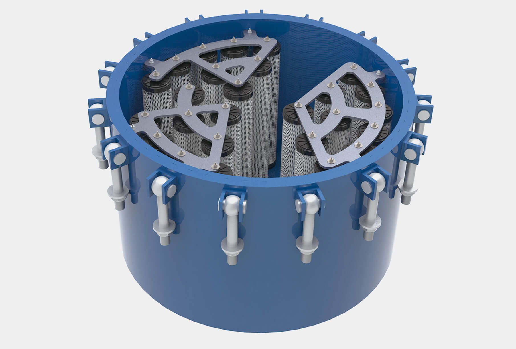
Typical Arrangements of Filter Elements
Gas-liquid and Liquid-Liquid Coalescers
Coalescers are used for gas-liquid or liquid-liquid separation. Coalescers are designed by the composition and type of contaminants on the flow media.
Coalescing filters are also used to prevent fine mists from entering the absorber. Liquid-gas coalesces are also used for removal of fine aerosols in gas production, processing and transmission. Coalesce cartridges, made of pleated glass fiber media supported by metal core, which has higher efficiency then traditional separators with mesh pads and vane packs. The reason is higher efficiency is that cartridges contain a much finer pore structure and larger surface area. Coalescers remove 99.5% solids 0.4 micron and larger.
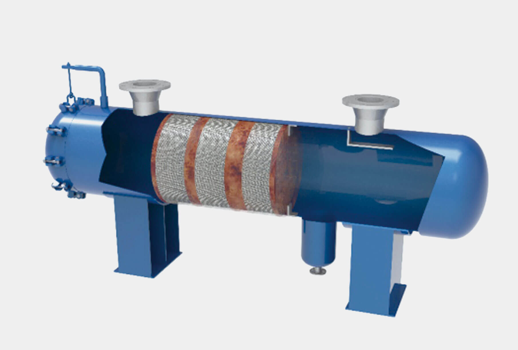
- Typical horizontal liquid phase coalescers
“Iron Sulfide from corrosion, can interfere with the liquid-liquid separation, thus the section of liquid collection acts as a holder for the liquids removed from the gas in the vessel upper sections”
Coalescing Filters, normally are vertical, used in natural gas pipelines to remove liquids from the flow streams, where very high gas-to-liquid ratios. Coalescing filters have only filter cartridges.

- Typical horizontal liquid phase coalescers

- Horizontal two-stage coalescing filters
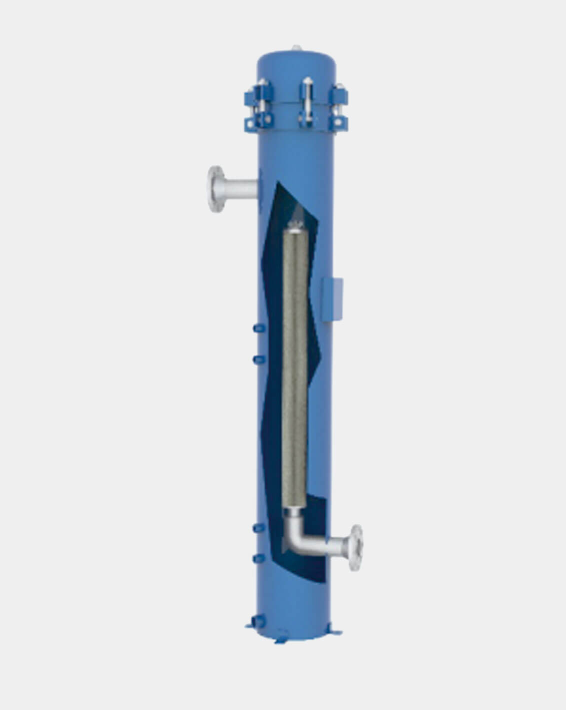
- Typical vertical liquid-liquid coalesce
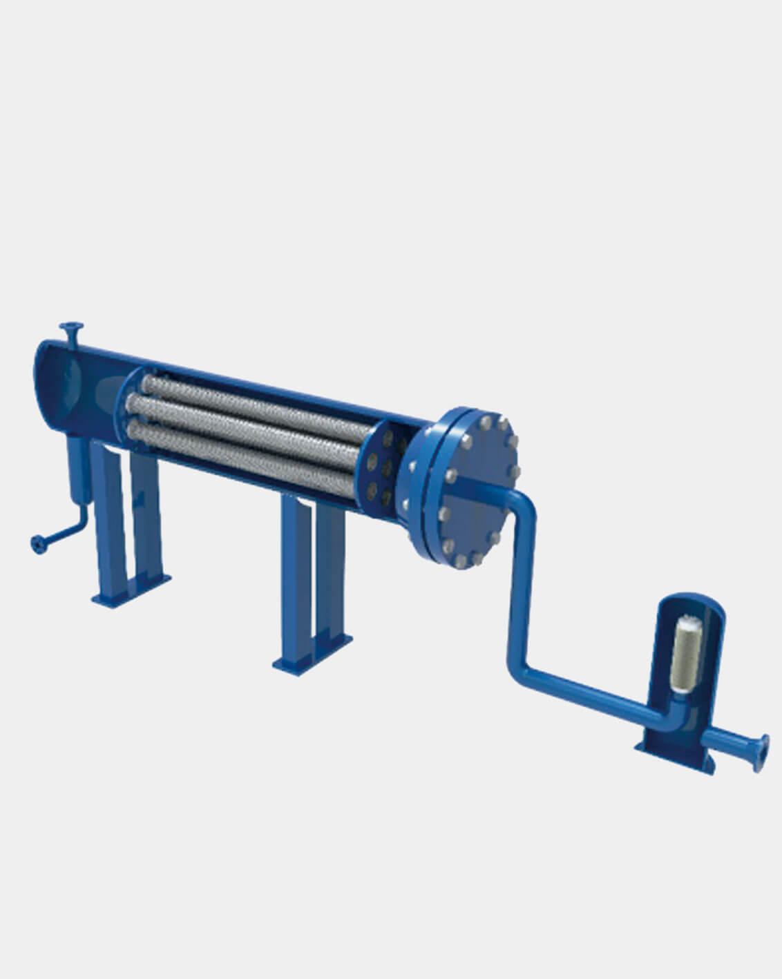
- Horizontal coalescer with prefiltering vessel
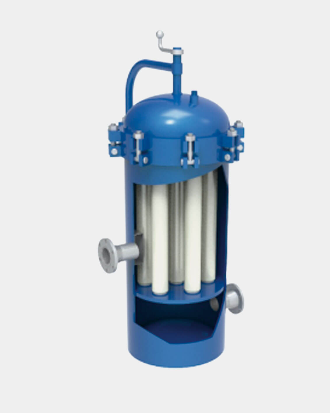
- Typical Cartridge Filter
Technical Parameters
| Design pressure |
Vessel size |
Gas Capacity MMSCFD |
| psi |
MPa |
inch x foot |
mm x mm |
400
PSIG |
600
PSIG |
800
PSIG |
1000
PSIG |
1200
PSIG |
1400
PSIG |
| 1440 |
9.9 |
16 x 8.5 |
406 x 2591 |
19 |
23 |
26 |
29 |
32 |
34 |
| 1440 |
9.9 |
20 x 8.5 |
508 x 2591 |
23 |
28 |
32 |
35 |
38 |
41 |
| 1440 |
9.9 |
20 x 10 |
508 x 3048 |
23 |
28 |
32 |
35 |
38 |
41 |
| 1440 |
9.9 |
24 x 12.5 |
610 x 3810 |
45 |
56 |
64 |
74 |
77 |
83 |
| 1440 |
9.9 |
30 x 12.5 |
762 x 3810 |
80 |
98 |
112 |
125 |
136 |
145 |
| 1440 |
9.9 |
36 x 12.5 |
914 x 3810 |
111 |
135 |
155 |
173 |
188 |
201 |
Features
- Skid-mounted
- Flanges
- API 14C rated (for offshore)
- Quick Opening Closure
- Manway
- Valve bypass
- Customized capacity ratings
- Sour service
- Controllers and indicators
- Flow control equipment
- Durable internals
- High-efficient filter elements
- 3-layer coating
- Insulation
- Fireproofing
- Electrical and signals lines
- Liquid boot
Benefits
- Efficient liquid removal
- Efficient solids removal
- Safe operation
- Fast filter replacement
- Easy maintenance
- Remote and local control
- Corrosion resistance
- Outdoor installation
- Adequate piping arrangement
- Spare filter elements and parts
- Space-saving
- Onshore and offshore application
Code & Standards
- ASME Sec VIII, U or U2
- NACE MR0175
- API 14C
- ASME B16.5 and ASME B16.47
- EN 10204 type 3.1
Testing & Inspection
- Non-Destructive Examination (NDE)
- Radiography (RT)
- Ultrasonic
- Magnetic Particle
- Dye Penetrant
- Function Test (for Closures)
- RMI Test
- Impact Test
- RWHT
- Special Heat Treatment
- Material Certification
- Hydrostatic Test
- Coating test & inspection
Application
- Gas pipelines
- Gas field treatments
- Metering & regulating stations
- Petrochemical plants
- Gas processing plants
- Chemical processing plants
Working Media
- Natural gas
- Methyl Chloride
- Methane
- Hydrogen
- Propane
- Propylene
- Helium
- Halocarbons
- Ethylene
- Ethane
- Carbon Monoxide
- Carbon Dioxide
- Ammonia
- Biogas
- Air


