


Test Separator
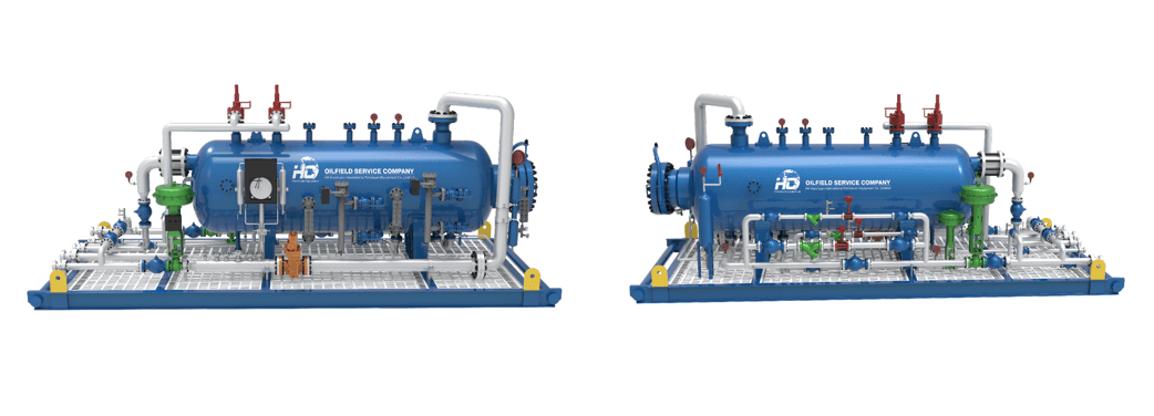
Test separator is an indispensable device in the exploration and development of onshore and offshore oil and gas fields. It is mainly used in well testing, well clean-ups and other flow operations for efficient and safe separation and measurement of oil, gas and water. According to the form can be divided into horizontal, vertical and spherical. Our 3P Test Separators usually supplied with high-accuracy instruments, control and shut-off valves, piping and skid, and referred as Test Separator Package / Module / Skid. Separator vessel is equipped with internal components, such as inlet deflector, vane pack, coalescer, wave breaker, weir plates, and mist extractor. Separator modular unit can be used both in offshore or onshore, either in standalone item or part of the package, and designed to fit the trailer for ensure fast and effective mobility during operation.
Our company's test separator adopts pressure controller, level controller and pneumatic control valve to achieve automatic control of pressure and liquid level of the metering separator, which can meet the well test requirements of various oil and gas fields. At present, it has been widely used in Changqing, Dagang, Jilin, Qinghai, Daqing and other oil fields in China and overseas oil fields such as Egypt, Myanmar, Algeria, Nigeria, Russia, and India, and has achieved good economic and social benefits.
The Test Separator is a highly efficient separator specifically designed for oilfield well testing applications. It employs advanced separation technology and processes to facilitate accurate fluid analysis and data acquisition. Renowned for its reliability, efficiency, and outstanding performance, our Test Separator has become the preferred equipment for major oilfield companies worldwide.
Our test separators are designed and manufactured in full compliance with international standards and are ASME certified. It has the following advantages:
1.Compact and reasonable structure design, integration of a variety of measuring instruments and control equipment;
2.Compatible with multiple control modes (direct + PLC + computer + DCS);
3.Multilevel security measures to ensure safe and reliable operation of the device;
4.In addition to standard products, we can also customize the most suitable design for customers according to their needs;
5.Reliable quality, which can be matched with components according to the customer's designated brand, such as instruments and valves;
6.It can meet GB, ASME, API and other national and industrial specifications at the same time.
HC is committed to becoming an industry leader in oilfield equipment. Our facilities are certified with ISO, API and ASME standards. Feel free to contact us for efficient and economical solutions.
The test separators price will change randomly with factors such as production cost, transportation cost, international situation, exchange rate, market supply and demand of raw materials. HC aims to provide you with high quality and best price well test separator.
If you are looking for a reliable, efficient, and high-performance well testing separator, HC will be your ideal partner. Our oil and gas separator provides accurate fluid analysis and data collection for oilfield well testing operations, enabling informed decision-making and improving operational efficiency.
Test Separator Basic parameters
Separator can be designed as per client’s operation conditions depending on flowrate, temperature, pressure, working medium and other operation data. Most of the clients, prefer size of 42 in. x 10 ft. and pressure of 1440 psi, for well test operation.
| Design pressure | Vessel size | Liquid Capacity | Dimensions(L x W x H) | Dimensions(L x W x H) | |||
| psi | bar | Mpa | inch x foot | cm | BOPD | ft | m |
| 800 | 55 | 5.5 | 34x8 | 86x244 | 3500 | 13x7x8.5 | 4.0x2.1x2.6 |
| 1440 | 99 | 10(9.93) | 30x10 | 76x305 | 3500 | 15x6.5x8 | 4.6x2.0x2.5 |
| 42x10 | 107x305 | 10000 | 15x7.5x9 | 4.6x2.3x2.7 | |||
| 42x15 | 107x457 | 12000 | 20x7.5x9 | 6.1x2.3x2.7 | |||
| 48x10 | 122x305 | 13000 | 15x8x9.5 | 4.6x2.5x2.9 | |||
| 48x12 | 122x366 | 19000 | 17x8x9.5 | 5.2x2.5x2.9 | |||
| 48x15 | 122x457 | 19000 | 20x8x9.5 | 6.1x2.5x2.9 | |||
| 2160 | 149 | 15(14.9) | 24x10 | 61x305 | 1000 | 15x4x7.5 | 4.6x1.2x2.3 |
| 42x15 | 107x457 | 12000 | 20x7.5x9 | 6.1x2.3x2.7 | |||
| 48x15 | 122x457 | 15000 | 20x8x9.5 | 6.1x2.5x2.9 | |||
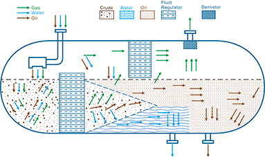
Process Principle of Oil-Gas-Water Three-Phase Separator
During oil and gas production, the extracted fluid from the wellhead is not a single stream of oil or gas, but rather a complex mixture composed of crude oil, natural gas, and water. To enable subsequent processing and utilization, these three components must be efficiently separated, which is achieved using a three-phase separator.
1. Working Principle
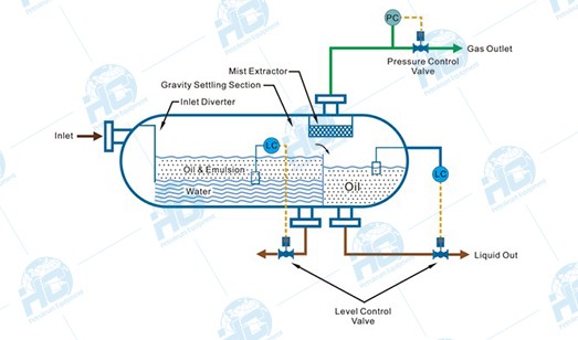
The three-phase separator mainly relies on gravity settling, fluid dynamics, and interface control to achieve the separation of oil, gas, and water:
l Gas Separation: After the mixed fluid enters the separator, the flow velocity decreases sharply. Due to its lowest density, natural gas rises quickly and is directed to the upper gas outlet.
l Liquid Stratification: The denser water settles at the bottom of the vessel, while the lighter crude oil floats above the water layer, forming a clear oil-water interface.
l Interface Control: With the aid of level gauges and interface controllers, the oil, gas, and water phases remain stably stratified inside the separator and are discharged separately through their respective outlets.
2. Main Structural Components
A standard three-phase separator is typically composed of the following parts:
- Shell (Pressure Vessel): Designed in horizontal or vertical orientation according to process requirements, generally cylindrical in shape, with pressure-resistant and corrosion-resistant properties.
- Inlet Device (Feed Distributor): Distributes the high-velocity mixed fluid evenly and reduces impact.
- Gas Separation Section: Located at the upper part of the vessel, often equipped with a demister or cyclone separator to remove liquid droplets entrained in the gas.
- Liquid Settling Section: Located at the middle and lower part, where oil and water are separated by gravity.
- Baffles / Coalescing Devices: Extend the retention time of liquids, promoting the coalescence and settling of small droplets.
- Interface Control System: Includes level gauges, interface sensors, and automatic liquid discharge control valves to maintain stable stratification of oil and water.
- Outlet Piping: Separate outlets are provided for the gas phase, oil, and water.
3. Working Process
Feed Diffusion: The mixed fluid enters through the inlet, and its flow rate drops sharply, causing most of the gas to immediately escape.
Preliminary Gas-Liquid Separation: The gas enters the upper space, passes through a demister to remove entrained liquid droplets, and is discharged through the gas outlet.
Oil-Water Stratification: Under gravity, the liquid naturally separates—water, being denser, settles at the bottom, while oil floats on top.
Interface Control: The oil-water interface height is maintained by a level control system to ensure stable separation.
Three-Phase Discharge: Gas, crude oil, and wastewater are discharged separately through their respective outlets and sent to subsequent processing stages.
Frequently Asked Questions
What is the difference between a test separator and a production separator?
A test separator is used for temporary well performance testing and production measurement, while a production separator is designed for continuous processing.
Should I choose a horizontal or vertical test separator?
Horizontal separators are generally preferred for high liquid volumes, while vertical separators are suitable for high gas fractions or limited installation space.
How do I size a test separator?
Separator sizing depends on flowrate, pressure, fluid composition, retention time, and separation efficiency requirements.
Can HC provide sour gas test separators?
Yes. HC can manufacture test separators for sour service applications according to NACE requirements.
Contact HC for Custom Test Separator Solutions
If you are planning a well testing project or need customized separation equipment for your oilfield operation, contact HC for technical support and engineering consultation.
